智能振动器使用的Gokit开发板
| 操作系统 | 云服务/平台 | 技术难度 | 关注领域 |
|---|---|---|---|
| RTOS | Gizwits Cloud | 中级 | Healthcare,Sensors |
任务目标
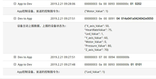
主要是使用安装在手机上的APP发送命令来控制Gokit4开发套件提供的振动器启动/停止振动。

智能振动器使用的Gokit开发板

使用数据线给开发板供电

APP可以发送控制命令来点亮/熄灭led

demo-Smart-viblitor的演示主要是使用安装在手机中的APP发送命令来控制Gokit4开发套件提供的振动器来启动/停止振动。
所需材料/所需清单/工具
• BG96
• Gokit4
• Led
源码/示例/可执行的应用程序
附加资料
• demo-Smart-vibration-motor-picture
搭建/在组装说明
使用的零件
以下是此项目中使用的项目。
1. development kit.手机里面安装机智云提供的通用的apk,用来查看本地上报的数据和控制Gokit4开发板提供的振动器。
2.Gokit4 development board.Gokit4开发板。
3.Usb data line数据线. supply power供电。
4.Win7 PC. windows 7 电脑。
部署项目
1.在机智云平台定义产品“智能振动器”,包括基本信息,数据点,硬件解决方案等。
2. 因为机智云平台现在不支持基于MDM9206平台生成代码。我们需要选择硬件平台“ESP_826632M”,然后做一些替换,替换可以参考上述连接。http://club.gizwits.com/thread-9395-1-1.html
3.添加将被上传到机智云的数据。
4.从链接处下载apk并安装。
5.注册移动物联网卡到NB-iot网络。
6.添加驱动相关代码。
7.编译代码,烧录镜像。
8.运行设备,打开设备并控制它。
9.若没有问题,上传代码到github。
工作流程
首先我们来看下gpio 和 motor的初始化。
demo-Smart-vibrator/main/main.c
void gagentMain( void )
{
getFreeHeap();
sensorInit();
gizwitsInit();
}
void sensorInit(void)
{
int32 ret = -1;
gizLog(LOG_INFO,"Sensor initialization ...\n");
led_init();
motor_init();
txm_module_object_allocate(&userTimer, sizeof(TX_TIMER));
ret = tx_timer_create(userTimer, "userTimer", userTimerCB, NULL, 1,
100, TX_AUTO_ACTIVATE);
if(ret != TX_SUCCESS)
{
gizLog(LOG_WARNING,"Failed to create UserTimer.\n");
}
}
void led_init()
{
gizLog(LOG_INFO,"in led_init ...\n");
led_gpio_config();
}
void motor_init()
{
gizLog(LOG_INFO,"in motor_init ...\n");
motor_gpio_config();
}
demo-Smart-vibrator/gpio/gpio.c
void led_gpio_config()
{
gizLog(LOG_INFO,"in led_gpio_config...\n");
gpio_config(GPIO_BLUE, QAPI_GPIO_OUTPUT_E, QAPI_GPIO_NO_PULL_E, QAPI_GPIO_2MA_E);
gpio_config(GPIO_RED, QAPI_GPIO_OUTPUT_E, QAPI_GPIO_NO_PULL_E, QAPI_GPIO_2MA_E);
gpio_config(GPIO_GREEN, QAPI_GPIO_OUTPUT_E, QAPI_GPIO_NO_PULL_E, QAPI_GPIO_2MA_E);
}
void motor_gpio_config()
{
gizLog(LOG_INFO,"in motor_gpio_config ...\n");
gpio_config(GPIO_MOTOR, QAPI_GPIO_OUTPUT_E, QAPI_GPIO_NO_PULL_E, QAPI_GPIO_2MA_E);
}
gpio_config: do some gpio initialization.做一些gpio的初始化。
void gpio_config(MODULE_PIN_ENUM m_pin,qapi_GPIO_Direction_t gpio_dir,qapi_GPIO_Pull_t gpio_pull,qapi_GPIO_Drive_t gpio_drive)
{
gizLog(LOG_INFO,"in gpio config.....\n");
qapi_Status_t status = QAPI_OK;
tlmm_config[m_pin].pin = gpio_map_tbl[m_pin].gpio_id;
tlmm_config[m_pin].func = gpio_map_tbl[m_pin].gpio_func;
tlmm_config[m_pin].dir = gpio_dir;
tlmm_config[m_pin].pull = gpio_pull;
tlmm_config[m_pin].drive = gpio_drive;
// the default here
status = qapi_TLMM_Get_Gpio_ID(&tlmm_config[m_pin], &gpio_id_tbl[m_pin]);
gizLog(LOG_INFO,"pin_num = %d, gpio_id[%d], status = %d ...\n",gpio_map_tbl[m_pin].pin_num, gpio_map_tbl[m_pin].gpio_id, status);
if (status == QAPI_OK)
{
status = qapi_TLMM_Config_Gpio(gpio_id_tbl[m_pin], &tlmm_config[m_pin]);
gizLog(LOG_INFO,"after qapi_TLMM_Config_Gpio, status = %d ...\n", status);
if (status != QAPI_OK)
{
gizLog(LOG_INFO,"gpio config failed.....\n");
}
status = qapi_TLMM_Drive_Gpio(gpio_id_tbl[m_pin], gpio_map_tbl[m_pin].gpio_id, QAPI_GPIO_HIGH_VALUE_E);
}
}
Process:
gizIssuedProcess ---> ACTION_CONTROL_DEVICE ---> gizDataPoint2Event ---> gizwitsEventProcess
gizIssuedProcess: the function is called by the gagent to receive the relevant protocol data delivered from the cloud or the app.该函数被gagent调用,接收来自云端或app端下发的相关协议数据。
int32_t ICACHE_FLASH_ATTR gizIssuedProcess(uint8_t *didPtr, uint8_t *inData, uint32_t inLen,uint8_t *outData,int32_t *outLen)
{
if((NULL == inData) || (NULL == outData) || (NULL == outLen))
{
gizLog(LOG_WARNING,"!!! IssuedProcess Error \n");
return -1;
}
if(NULL == didPtr)
{
gizLog(LOG_INFO,"~~~gizIssuedProcess: did is NULL .\n");
}
else
{
gizLog(LOG_INFO,"~~~gizIssuedProcess: did %s\n", didPtr);
}
if(NULL == didPtr)
{
switch(inData[0])
{
case ACTION_CONTROL_DEVICE:
gizDataPoint2Event((gizwitsIssued_t *)&inData[1], &gizwitsProtocol.issuedProcessEvent,&gizwitsProtocol.gizCurrentDataPoint);
gizwitsEventProcess(&gizwitsProtocol.issuedProcessEvent, (uint8_t *)&gizwitsProtocol.gizCurrentDataPoint, sizeof(dataPoint_t));
gizMemset((uint8_t *)&gizwitsProtocol.issuedProcessEvent, 0, sizeof(eventInfo_t));
*outLen = 0;
break;
case ACTION_READ_DEV_STATUS:
gizDataPoints2ReportData(&gizwitsProtocol.gizLastDataPoint,&gizwitsProtocol.reportData.devStatus);
gizwitsProtocol.reportData.action = ACTION_READ_DEV_STATUS_ACK;
gizMemcpy(outData, (uint8_t *)&gizwitsProtocol.reportData, sizeof(gizwitsReport_t));
*outLen = sizeof(gizwitsReport_t);
gizLog(LOG_INFO,"%s: ", "~~~ReadReport \n");
//printf_bufs((uint8_t *)outData,*outLen);
break;
case ACTION_W2D_TRANSPARENT_DATA:
gizMemcpy(gizwitsProtocol.transparentBuff, &inData[1], inLen-1);
gizwitsProtocol.transparentLen = inLen-1;
gizwitsProtocol.issuedProcessEvent.event[0] = TRANSPARENT_DATA;
gizwitsProtocol.issuedProcessEvent.num = 1;
gizwitsEventProcess(&gizwitsProtocol.issuedProcessEvent, (uint8_t *)gizwitsProtocol.transparentBuff, gizwitsProtocol.transparentLen);
gizMemset((uint8_t *)&gizwitsProtocol.issuedProcessEvent, 0, sizeof(eventInfo_t));
gizMemset((uint8_t *)gizwitsProtocol.transparentBuff, 0, BUFFER_LEN_MAX);
gizwitsProtocol.transparentLen = 0;
*outLen = 0;
break;
default:
break;
}
}
else
{
gizLog(LOG_WARNING," Error : didPtr \n");
}
return 0;
}
ACTION_CONTROL_DEVICE: Perform related processing of "controlled protocol". 进行“控制型协议”的相关处理。
gizDataPoint2Event: Generate "control events" according to the protocol and complete the conversion of the corresponding data type.根据协议生成“控制型事件”,并完成相应数据类型的转换。
static int8_t ICACHE_FLASH_ATTR gizDataPoint2Event(gizwitsIssued_t *issuedData, eventInfo_t *info, dataPoint_t *dataPoints)
{
if((NULL == issuedData) || (NULL == info) ||(NULL == dataPoints))
{
gizLog(LOG_WARNING,"gizDataPoint2Event Error , Illegal Param\n");
return -1;
}
if(sizeof(issuedData->attrFlags) > 1)
{
if(-1 == gizByteOrderExchange((uint8_t *)&issuedData->attrFlags,sizeof(attrFlags_t)))
{
gizLog(LOG_WARNING,"gizByteOrderExchange Error\n");
return -1;
}
}
if(0x01 == issuedData->attrFlags.flagLed_Value)
{
info->event[info->num] = EVENT_Led_Value;
info->num++;
dataPoints->valueLed_Value = gizStandardDecompressionValue(Led_Value_BYTEOFFSET,Led_Value_BITOFFSET,Led_Value_LEN,(uint8_t *)&issuedData->attrVals.wBitBuf,sizeof(issuedData->attrVals.wBitBuf));
}
if(0x01 == issuedData->attrFlags.flagMotor_Value)
{
info->event[info->num] = EVENT_Motor_Value;
info->num++;
dataPoints->valueMotor_Value = gizStandardDecompressionValue(Motor_Value_BYTEOFFSET,Motor_Value_BITOFFSET,Motor_Value_LEN,(uint8_t *)&issuedData->attrVals.wBitBuf,sizeof(issuedData->attrVals.wBitBuf));
}
return 0;
}
gizwitsEventProcess: corresponding event processing according to the generated "control event" ( calling the corresponding driver function)根据已生成的“控制型事件”进行相应事件处理(调用相应的驱动函数)
int8_t ICACHE_FLASH_ATTR gizwitsEventProcess(eventInfo_t *info, uint8_t *data, uint32_t len)
{
uint8_t i = 0;
dataPoint_t * dataPointPtr = (dataPoint_t *)data;
moduleStatusInfo_t * wifiData = (moduleStatusInfo_t *)data;
if((NULL == info) || (NULL == data))
{
gizLog(LOG_WARNING,"!!! gizwitsEventProcess Error \n");
return -1;
}
for(i = 0; i < info->num; i++)
{
switch(info->event[i])
{
case EVENT_Led_Value :
currentDataPoint.valueLed_Value = dataPointPtr->valueLed_Value;
gizLog(LOG_INFO, "Evt: EVENT_LedValue %d \n", currentDataPoint.valueLed_Value);
if(0x01 == currentDataPoint.valueLed_Value)
{
//on led
gpio_high_low(true,GPIO_GREEN);
}
else
{
//off led
gpio_high_low(false, GPIO_GREEN);
}
break;
case EVENT_Motor_Value :
currentDataPoint.valueMotor_Value = dataPointPtr->valueMotor_Value;
gizLog(LOG_INFO,"Evt: EVENT_MotorValue %d \n", currentDataPoint.valueMotor_Value
);
if(0x01 == currentDataPoint.valueMotor_Value)
{
//start motor
gpio_high_low(true,GPIO_MOTOR);
}
else
{
//stop motor
gpio_high_low(false,GPIO_MOTOR);
}
break;
......
default:
break;
}
}
gizSendQueue(SIG_UPGRADE_DATA);
return 0;
}
gpio_high_low: mainly to control led or motor by setting the high/low level to the corresponding pin.主要是通过设置相应引脚电平高/低来控制led和motor.
void gpio_high_low(bool on, uint8_t pin_gpio)
{
if (on)
{
qapi_TLMM_Drive_Gpio(gpio_id_tbl[pin_gpio], gpio_map_tbl[pin_gpio].gpio_id, QAPI_GPIO_LOW_VALUE_E);
}
else
{
qapi_TLMM_Drive_Gpio(gpio_id_tbl[pin_gpio], gpio_map_tbl[pin_gpio].gpio_id, QAPI_GPImotor_gpio_configO_HIGH_VALUE_E);
<p> }</p>
<p>}</p>
1.从该链接地址处下载代码。
2.编译代码,烧录镜像到Gokit4开发板。
3.USB数据线连接PC机和Gokit4开发板。
4.打开串口调试助手。
5.点击机智云平台上的设备日志以查看设备是否上线。
6.当设备上线,你可以点击查看按钮,就可以看见来自本地数据被上传的机智云端了。
7.从链接地址处下载APP,并安装到手机。
8.打开APP,你可以看见“我的设备”,在这里你可以通过扫描二维码找到你的设备。
9.接下来,生成二维码。
a.打开GIZ_SerialTool.exe。
b.选择“小工具”,点击“二维码生成”,输入“Product Key”和“MAC地址或者IMEI号”。
c.点击“获得二维码”,等一会儿,你就可以看到二维码。
10.点击“我的设备”,扫描二维码,你就可以找到你的设备。
11.然后控制设备,查看数据。
贡献者信息
| 姓名 | 公司 |
|---|---|
|
Zhen sunzhen@thundersoft.com |
Thundersoft |
|
Rong yangrong0925@thundersoft.com |
Thundersoft |
|
Jie wangjie0508@thundersoft.com |
Thundersoft |
|
Kou kouzw0723@thundersoft.com |
Thundersoft |
|
Eric yansh0810@thundersoft.com |
Thundersoft |
>>浏览更多Qualcomm硬件案例:http://qualcomm.csdn.net/m/zone/qualcomm2016/project
Qualcomm 开发者专区是 Qualcomm 联合CSDN 共同打造的面向中国开发者的技术专区。致力于通过提供全球最新资讯和最多元的技术资源及支持,为开发者们打造全面一流的开发环境。本专区将以嵌入式、物联网、游戏开发、Qualcomm® 骁龙™处理器的软件优化等技术为核心,打造全面的开发者技术服务社区,为下一代高性能体验和设计带来更多的想法和灵感。
加入 Qualcomm 开发者专区


申请成为“Qualcomm荣誉技术大使”
“Qualcomm荣誉技术大使”是Qualcomm开发者社区对开发者用户技术能力与影响力的认证体现,该荣誉代表Qualcomm社区对用户贡献的认可与肯定。
立即申请招贤纳士
Qualcomm在中国的业务发展迅速,每年提供大量的技术岗位,分布在北京,上海,深圳等地。Qualcomm开发者社区是开发者藏龙卧虎之地,Qualcomm中国HR特别设立了招聘通道,欢迎开发者同学踊跃报名。
Qualcomm 活动 更多
6月19日
线上
